Influence of the focal length of the silicon lens to the THz bottle beam. (a) Presents the Examplitude and wrapped phase cross-sections with α = 20° and f = 8 mm on the x-z plane. (b)Shows the longitudinal Ex amplitude and wrapped phase patterns with α = 20° and f = 11 mm. (c,e) Give the amplitude curves with f = 8 mm and 11 mm along the lines of z = 0 mm and x = 0 mm. (d) Shows the transverse phase curves with f = 8 mm and 11 mm along the lines of z = 0 mm. (f) Plot the longitudinal phase curves with f = 8 mm and 11 mm on the corresponding amplitude maximal positions.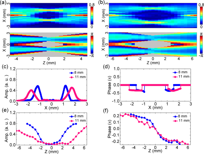
Herein,
we still want to simply discuss similarities and differences between
THz special beams carrying orbital angular momentum (OAM) and the THz
bottle beam. Currently, various THz beams carrying OAM have been paid
more and more attentions due to their important application potentials
in THz imaging and communications, such as Bessel, Laguerre-Gaussian,
and Airy beams with high-order topological charges. Analogous to the THz
bottle beam, these THz beams also have a hollow-core intensity25.
However, the discrepancy between these THz beams and the THz bottle
beam is that the central intensity nulls of these THz beams are
originated from their phase singularities, so their central
zero-amplitude zones are in two dimensions. Meanwhile, the dark focus of
the THz bottle beam is due to the interference effect of converging or
diverging THz beams so that the THz optical capsule is formed in three
dimensions. Therefore, researchers prefer to classify these THz beams
carrying OAM as the THz hollow beam. Actually, the optical bottle beam
carrying OAM has been also investigated in 2015. Interestingly, the
radius of the central annular amplitude is fixed with varying the
topological charge for an optical bottle beam carrying OAM, so this kind
of optical beam is called as “perfect vortex beam”21.
To be honest, diffraction characteristics of these special THz beams
have been underutilized, which leaves much room for the development of
the future THz technology. In
conclusion, the THz bottle beam is generated by utilizing a Teflon
axicon and a silicon lens. The complex field of the THz bottle beam are
coherently characterized by applying the THz imaging system with a
focal-plane array and the evolution process of the THz field is
detailedly recorded by implementing the Z-scan measurement. For a
linearly polarized THz bottle beam, Ex exhibits
the amplitude distribution of a Bessel-like beam and the
doughnut-shaped optical barrier on the two terminals and the
intermediate section of the optical bottle. Besides, the Ex phase
pattern shows the converging as well as diverging processes of the THz
beam refracted by the Teflon axicon after passing through the silicon
lens and manifests the formation origin of the THz bottle beam. Besides,
the Ez component
of the THz bottle beam is measured and analyzed by applying the vector
measurement function of the THz imaging system. The Ez component
with a linear or a circular polarization separately shows a double-lobe
characteristics or a vortex pattern. By adopting the vectorial
diffraction algorithm, the complex field characteristics of the Ex and Ez components
are exactly simulated. Finally, performance tuning of the THz bottle
beam is achieved by adjusting the parameters of the Teflon axicon and
the silicon lens. The switch of the optical barrier can be easily
controlled by varying distance the between the Teflon axicon and the
silicon lens. With decreasing the base angle of the Teflon axicon or the
focal length of the silicon lens, the THz bottle beam shows a stronger
optical barrier and a smaller central dark focus. In a nutshell, this
work describes the vector characteristics of the THz bottle beam in
detail and achieves the modulations to the features of the THz beam. We
consider that the work is helpful for the application and development of
the THz technology in particle manipulation and microscopy. In
addition, these experimental laws and theoretical discussions can be
readily transferred to the infrared, visible, and other frequency
ranges. To
observe the characteristics of a THz bottle beam, a THz imaging system
with a focal-plane array is utilized to acquire the complex field of the
THz beam, including amplitude and phase information. Figure 1apresents
the schematics of the experimental setup. The light source is a
Spectra-Physics femtosecond laser amplifier with a central wavelength of
800 nm, a pulse duration of 50 fs, a repetition ratio of 1 kHz, and an
average power of 700 mW. The incoming laser is divided into the exciting
and detecting beams for the generation and detection of the THz
radiation. The average powers of the exciting and detecting beams are
690 mW and 10 mW, respectively. Firstly, a concave lens (L1) with a
focal length of 50 mm is used to expand the exciting beam and a
<110> ZnTe crystal with a thickness of 3 mm is chosen as the THz
source. After the exciting beam passing through the ZnTe crystal, a THz
beam with an x-linear polarization is generated by the optical
rectification26.
Then, the THz beam is collimated by a parabolic mirror (PM) with a
focal length of 100 mm for forming a THz quasi-plane wave. The
collimated THz beam possesses a diameter of 14 mm. A Teflon axicon and a
silicon lens are used as the wave front modulators for generating a THz
bottle beam, as shown in Fig. 1b.
The incident THz beam successively passes through them to form the
peculiar THz field. The out-going THz field illuminates a sensor crystal
for detecting the complex THz field. In the path of the detecting beam,
a polarizer (P) is used to ensure the probe polarization. The detecting
beam is reflected onto the sensor crystal by a non-polarization beam
splitter with a 50/50 ratio. In the sensor crystal, the probe
polarization is modulated by the THz field to carry the two-dimensional
THz information due to the Pockels effect27.
Then, an imaging module is adopted to receive the reflected detecting
beam, which is composed of a lens (L2), a quarter wave plate (QWP), a
Wollaston prism (PBS), a lens (L3), and a CCD camera. A mechanical
chopper is used to modulate the output frequency of the exciting beam. A
balanced detection method28 and a dynamics subtraction technique29 are
utilized to remove the background intensity of the detecting beam. A
series of THz temporal images are acquired by adjusting the relative
delay between the THz and detecting beams and the THz images in the
frequency domain are extracted by operating the Fourier transformation. To
reconstruct the evolution process of a THz bottle beam, the Teflon
axicon and the silicon lens are mounted on a motorized translation stage
to fulfill a Z-scan measurement. The focal point of the silicon lens is
viewed as the base point. The diffraction process of the THz beam is
recorded from z = −4.5 mm to z = 4.5 mm and the scanning step is set as
0.5 mm. The advantage of the measurement scheme is that the optical path
of the THz beam is fixed, so the linear phase term exp(jkz) of
the THz wave is negligible. Besides, a quartz TQWP with a central
wavelength of 385 μm and a bandwidth of 200 μm is utilized to adjust the
THz polarization for observing the discrepancies between the linearly
and circularly polarized THz bottle beams. To
comprehensively observe the vector characteristics of a THz bottle
beam, the different polarization components need to be separately
measured, including the transverse (Ex) and longitudinal (Ez)
components. In the experiment, a ZnTe crystal with
a <110> crystalline orientation and a 1 mm thickness is picked up
as the sensor crystal to measure Ex.
The angle between the <001> axis of the crystal and the
polarization direction of the detecting beam and is fixed as 0° to
maximize the detection efficiency30. To acquire the Ez component,
a ZnTe crystal with a <100> crystalline orientation and a 1 mm
thickness is chosen as the sensor crystal. The angle between the
<010> axis of the crystal and the polarization direction of the
detecting beam is adjusted as 45° for optimizing the detection
efficiency31.
Herein, it should be noted that both of <110> and <100>
ZnTe crystals have the identical detection sensitivities to the THz
field32.Discussion
Methods
 首页
首页


