Hua Li, 1 Wen-Jian Wan,1 Zhi-Yong Tan,1 Zhang-Long Fu,1 Hai-Xia Wang,1 Tao Zhou,1 Zi-Ping Li,1 Chang Wang,1Xu-Guang Guo,2 and Jun-Cheng Cao1
太赫兹波的频率定义在0.1和10太赫兹之间,由于其独特的特性,如纸张和塑料材料的透明性,各种化学物质的丰富吸收“指纹”以及潜在的超宽通信带宽,引起了人们极大的兴趣。在过去几十年中,太赫兹辐射源(如量子级联激光器(QCL),单载波光电二极管,倍频器等)和探测器(热电,测辐射热计,Golay-cell高莱等等)导致了太赫兹技术的显着进步。例如太赫兹成像,数据传输和光谱学的实验室应用已经被证实。太赫兹技术的进一步发展要求快速检测千兆赫调频太赫兹辐射。快速太赫兹检测器是实现快速太赫兹应用的最后一个组件,因为使用量子级联设计的太赫兹源已经被验证可以快速调制到35 GHz 。对于太赫兹探测器,大多数工作在低调制频率(几十或几百赫兹)的热红外探测器因此不能检测到快速调制的太赫兹波。然而,由于在皮秒级别的快载流子弛豫时间,所以采用电子互带跃迁的量子阱光探测器(QWP)应该在太赫兹区域中快速工作。实际上在中红外波长范围内,采用空气桥技术和共面波导结构,已经在2006年已经展示了带有小台面量子阱红外光电探测器的室温110GHz高频外差探测。然而,在太赫兹状态下,由于衍射极限的原因,耦合到小型QWP器件的太赫兹光相对困难。因此,太赫兹QWP的高频微波操作尚未见报道。
在这项工作中,利用精心设计的微波传输线有效提取射频(RF)信号,我们首先展示了使用太赫兹QWP(器件面积为400×400μm2)的GHz调制太赫兹辐射的快速检测。电整流测量显示,QWP器件具有高达4.3GHz的调制响应带宽。作为快速检测的证明,使用快速太赫兹QWP,从长腔太赫兹QCL发射的6.2GHz调制太赫兹光被成功地用于模间光学拍音频谱的检测。
更多太赫兹QCL系统产品信息联系我们,sales@gamtic.com,021-5197 0121
The terahertz wave1 with the frequency defined between 0.1 and 10 THz is of great interest due to its unique properties such as transparency for papers and plastic materials, abundant absorption “fingerprints” of various chemicals, and potential large communication bandwidth. In the previous dozens of years, the fast development of terahertz radiation sources (such as quantum cascade lasers (QCLs)2, 3, uni-travelling-carrier photodiodes4, frequency multipliers5, etc.) and detectors (pyroelectrics6, bolometers7, Golay-cell8, etc.) results in a significant progress of terahertz technology. Laboratory applications for example the terahertz imaging, data transmission, and spectroscopy have been already demonstrated9–13. Further advances in terahertz technology require fast detection of gigahertz frequency modulated terahertz radiation. The fast terahertz detector is the last component for implementing fast terahertz applications since the terahertz source employing the quantum cascade design has been already verified for being fast modulated upto 35 GHz14. Regarding the terahertz detectors, most thermal infrared detectors working at low modulation frequencies (dozens or hundreds of Hz) are therefore not able to detect the fast modulated terahertz wave. However, the quantum well photodectors (QWPs)15, 16 employing the electron intersubband transitions are supposed to work fast in the terahertz region due to the fast carrier relaxation time in picoseconds level. Actually in the mid-infrared wavelength range, room temperature high frequency heterodyne detection upto 110 GHz with small mesa quantum well infrared photodetectors has been already demonstrated in 2006 employing the air bridge technique and coplanar waveguide configuration17. However, in the terahertz regime, due to the diffraction limit the terahertz light coupling to a small QWP device is relatively difficult. And therefore, the high microwave frequency operation of terahertz QWP has been not yet reported.
Here in this work by utilizing a carefully designed microwave transmission line to efficiently extract the radio frequency (RF) signal, we first demonstrate the fast detection of GHz-modulated terahertz radiation using a terahertz QWP with a device area of 400 × 400 μm2. The electrical rectification measurements reveal that the QWP device has a modulation response bandwidth upto 4.3 GHz. As a proof for the fast detection, a 6.2-GHz modulated terahertz light emitted from a long cavity terahertz QCL was successfully detected in terms of inter-mode optical beat note spectrum using the fast terahertz QWP.
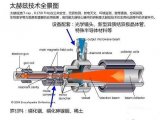
Figure 1 shows the experimental setup employed for the fast terahertz detection. The terahertz light is generated from an electrically-pump terahertz QCL. Due to the resonant cavity, the laser light is inherently modulated by the cavity round trip frequency of ~c/2ln with c being the speed of light, l the cavity length, and n the refractive index. Two parabolic mirrors are used to collect and focus the terahertz light onto the QWP. To couple the polarized terahertz light into the QWP mesa, a 45° edge facet geometry is used. To facilitate the extraction of the high frequency signal from the terahertz QWP mesa, a 50-Ω microwave transmission line is mounted as close as possible to the QWP mesa as shown in Fig. 1. The transmission line consists of an AlN dielectric substrate which is gold-coated on the backside and a thin metallic layer gold on top of the substrate. To efficiently collect the microwave signal via the transmission line, the design criteria is to make the dielectric layer the same thickness as the terahertz chip thickness around 200 μm and in the meantime set the transmission line impedance to 50-Ω by adapting the width of the metallic line. The top contact of the QWP mesa is wire bonded and connected to the central strip line while the back contact to the gold-plated holes which are connected to the ground. To reduce the microwave signal attenuation as much as possible and apply voltage onto the QWP mesa, high performance coaxial radio frequency cables (Huber + Suhner Sucoflex 100) and SMA connectors are used. A bias-T with a bandwidth of 40 GHz and DC current limit of 0.5A is used to inject DC voltage to the QWP and simultaneously extract the high frequency signal via the AC port. The weak microwave signal is firstly amplified by a low noise amplifier with a gain of 30 dB and then sent to a spectrum analyser (upto 26.5 GHz) for characterizations.

Experimental setup of the fast terahertz detection using a microwave transmission line equipped terahertz QWP. The modulated terahertz light is generated from a 6-mm long cavity terahertz QCL working in continuous wave mode. Two off-axis parabolic (OAP) ...
The lower left inset of Fig. 1 shows the focused terahertz beam pattern measured by replacing the QWP with a terahertz imager. It can be seen that with two parabolic mirrors, the terahertz light can be focused in a quasi-Gaussian area at the focus of the second parabolic mirror. The vertical and horizontal widths of the beam pattern are measured to be 290 and 210 μm, respectively, whilst the wavelength of the laser emission is around 71 μm. The upper right inset figure shows the schematic geometry of the QWP chip as well as the incident terahertz wave. If we ideally assume the incident terahertz beam has a gaussian pattern with a diameter of d = 300 μm, the side length of the square mesa is supposed to be 2√d≈420 μm to fully absorb the incident terahertz emission. Because of this, we finally choose the mesa area of 400 × 400 μm2in this work to balance the trade-off between photoresponse and device capacitance.
 首页
首页